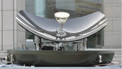
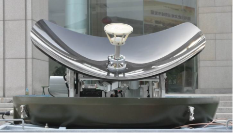
0.8m Ku Band COTM Antenna
Product Details
System Description
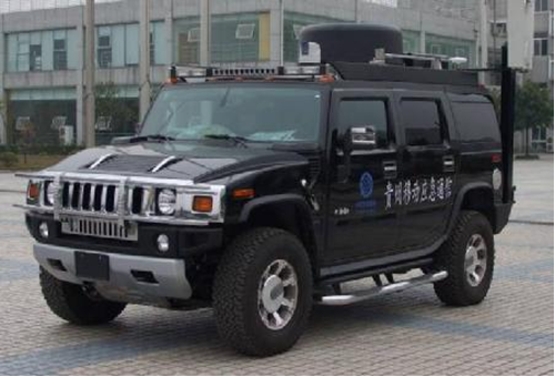
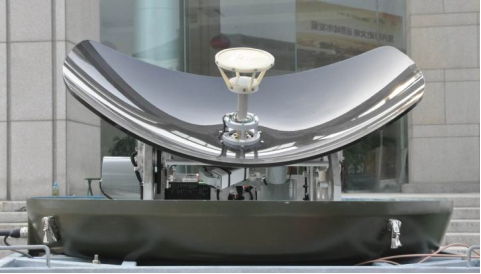
0.8m COTM Antenna Emergency Communication Vehicle
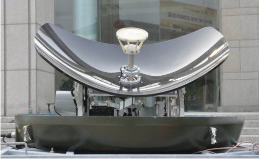
0.8m Ku-band parabolic COTM antenna
System Specifications
Antenna Aperture | 0.8m | |
Antenna Type | Double Correction Ring Focus Parabolic Antenna | |
Operating Frequency | Rx | 10.70~11.45GHz |
Tx | 12.75~13.25GHz | |
Gain | Rx | 36.59 dBi |
Tx | 37.98 dBi | |
VSWR | Rx | 1.25(At LNB port) |
Tx | 1.25(At HPA port) | |
-3dB beam width | Rx | 2.2° |
Tx | 1.7° | |
Noise Temperature | 65K (10° EL) | |
Port | WR-75 | |
Rx to Tx Isolation (dB) | ≥90 (including TRF) | |
Power Capacity | 500W | |
Antenna Cover Loss | ≤0.5 dB | |
Polarization | Linear polarization, automatic adjustment | |
XPD | ≥30dB (along the axis), ≥25dB (-1dB range) | |
First Side Lobe | ≤ -12 dB | |
Azimuth Range | 360°, Continuous Infinite Rotation | |
Elevation Range | 15°~90° | |
Polarization Range | ±90° | |
Driving Speed | 150Km/h | |
Capture Time | Initial Capture Time | ≤120s (platform does not move) |
Target Lost Time≤3min | ≤3s | |
Maximum Angle velocity | Az≥ 100º/s | |
EL≥ 80º/s | ||
POL≥60º/s | ||
Maximum Angle acceleration | Az≥800º/s² | |
EL≥ 800º/s² | ||
POL≥100º/s² | ||
Operating Temperature | -40℃ ~ +55℃(outdoor) | |
-25℃ ~ +55℃(indoor) | ||
Power supply | 220VAC,50Hz | |
Power consumption | ≤350W | |
Installation
The system is divided into four parts for installation: antenna and turntable, power amplifier, inertial navigation, ACU control unit. Among them, the ACU control unit (1U19 inch standard cabinet mounted on the rack) is installed on the cabinet in the car, and the rest of the components are installed on the roof.
Antenna Installation.
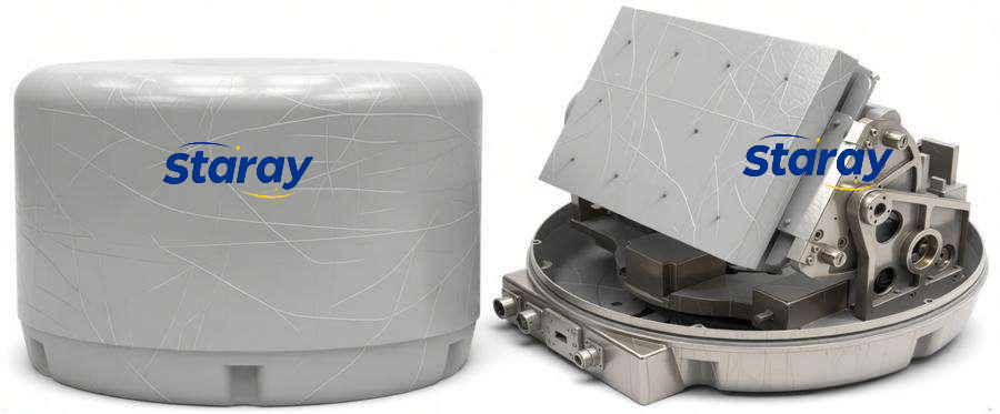
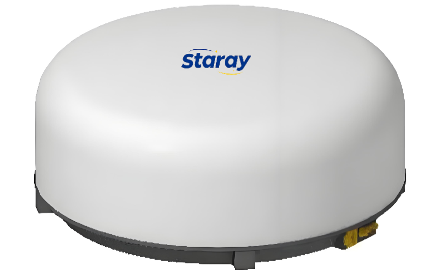
0.8m antenna appearance and size see below figures. When installing, M8*8 bolts are used to connect with the roof. Threaded holes are reserved on the mounting frame, and the hole depth is greater than 10mm. Three cable interfaces (one to the in-vehicle modem, one to the INS, and one to the ACU) and one waveguide interface (WR 75, to the BUC) are left on the antenna base.
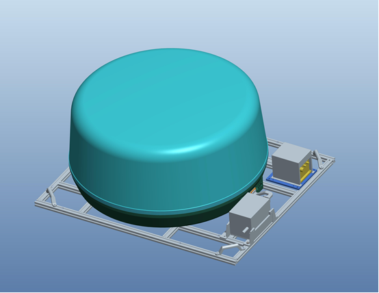
Figure1 Antenna Appearance
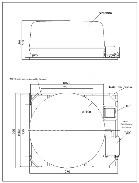
Figure 2 Antenna Size
ACU Installation
ACU control cabinet (1U standard cabinet): Connected to the cabinet inside the vehicle, the panel uses M5*4 screws, and is connected to the cabinet. The cabinet depth is 400mm.
Cables Connection
l There are 4 cables from inside the vehicle to outside. The thickest one has a diameter of ≤ 10mm. Two of them are connected to the power amplifier (one for power supply and the other from the modem to the input port of the power amplifier), and the other two are connected to the antenna (one for downlink from the antenna to inside the vehicle, and the other connected to the ACU control port).
l The L-band coaxial cable coming from outside the vehicle first connects to the power divider. The power divider requires a direct current isolation function and is connected to the coaxial cable port of the ACU (with SMA connector); one of the power divider's lines connects to the modem (the modem supplies power to the LNB through the power divider).